A digital alt-azimuth telescope drive
This is what I was able to build from Mel Bartels' design, based on the plans and software he has generously placed on his web site. http://www.efn.org/~mbartels/ A heartfelt thank you, Mel.
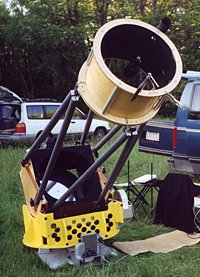
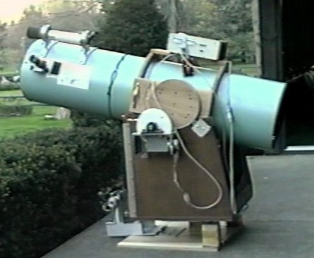
Leanne, my 20" f5 scope, set up near the summit of Spruce Knob WV, the finest dark-sky site in the East.
On the images below, click for a full-size pic
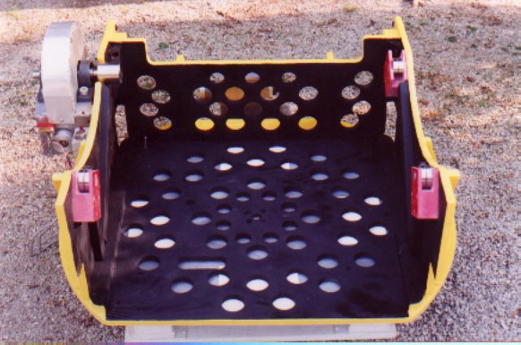
The new rocker box is much lighter, and cools faster after a session with a hole saw. The bearings are from a Xerox machine
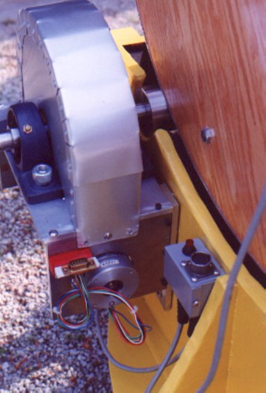
Here's the altitude roller drive assembly. The stepper drives a 240 tooth worm and 12:1 roller drive at 0.16 arcseconds per microstep.
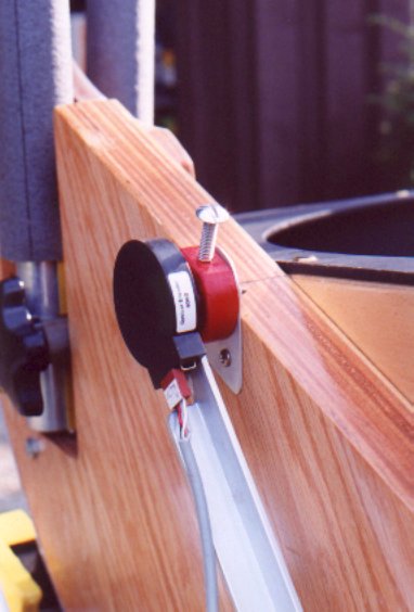
The 4000-step altitude encoder is mounted to one of the plywood donuts left over from the holesaw ventilation session.
I originally built the drive for my 12.5" scope, pictured below. I built the parts into the new rocker box for the 20" f5 truss-tube scope after I sold the 12.5" OTA
Here's the old 12.5" f5 scope on the platform at "first slew", before the paint job.
![]() Click for the sound of a half-stepping azimuth slew (452k WAV)
Click for the sound of a half-stepping azimuth slew (452k WAV)
![]() Click for the sound of dual axis microstepping with guiding adjustments (213k WAV)
Click for the sound of dual axis microstepping with guiding adjustments (213k WAV)
(You can hear that the robins in the trees make more noise than the scope drive)
The altitude stepper drive is a 200 step, 7 volt AstroSyn stepper motor, driven by computer-synthesized PWM microstepping at 10 microsteps per step. The motor turns a worm against a 240 tooth high density polyethylene (HDPE) gear. The gear is connected through a hub and shaft to a machined roller which provides another ten-to-one reduction. The azimuth drive has the same ratios, but the final roller reduction is through a linear tapered brass roller, driving the underside of the 24" diameter aluminum alloy base plate.
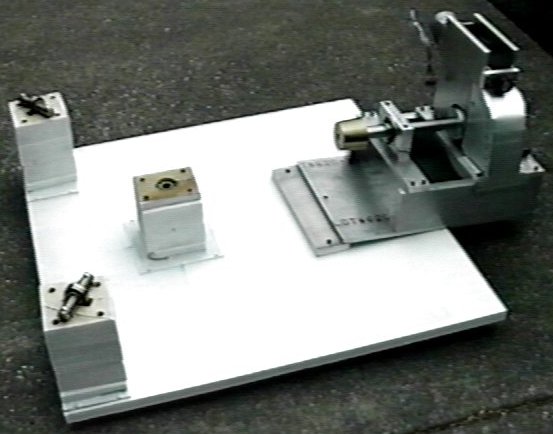
The altitude drive, showing the 240 tooth HDPE gear without it's protective cover. The assembly is made from 1/4" aluminum sheet, fastened by Allen head cap screws. One of the three bearings for the elevation trunnions (plywood disks) can be seen at the upper right. These are made from bearings and shafting from a Xerox machine I dismantled.
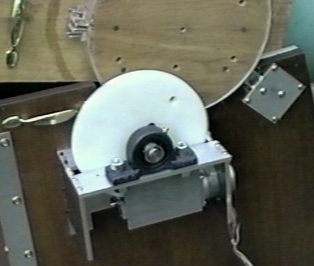
Another view of the altitude drive, showing both pillow block bearings and the aluminum facing on the elevation trunnion
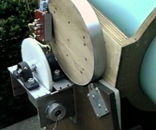
The azimuth drive, showing the stepper motor. A 90 degree slew takes 4 minutes. I might be able to tune it to run faster.
The azimuth drive, top view showing the worm. The end of the worm drive shaft opposite the stepper turns in a precision bearing.

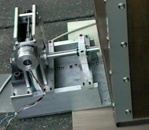
Base of the azimuth drive. The three precision bearings came from a Xerox machine. The pillars are glued and screwed 2x4 pine and plywood. Adjustable leveling feet in tee nuts are on the underside, below the three bearing points. The diameter of the large worm gear dictates the minimum height of the azimuth base. The top surface of the aluminum disk is 8 inches from the ground, compared to the 6 inch height of my equatorial platform.
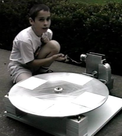
Here's the complete azimuth drive with my son, Thomas for scale. The disk is 1/4" 6061 aluminum, cut with a sabre saw. The white friction patches are textured rubber cut from the paper feed belt of the Xerox machine, glued with Pliobond contact cement. This keeps the Formica bottom of the scope rocker box from slipping. The rocker box works on this platform or my Shaw equatorial platform without modification.
The electronics box interfaces PC parallel port signal levels to the stepper windings and the hand pendant. The two meters were modified with shunts to read the current to each motor. I also added an MG-III encoder interface board inside the cabinet, interfaced through the PC serial port. It's powered from a 15volt DC power supply or a 12 volt battery (battery assumes a laptop PC). You can see the parallel and the serial connectors on the right of the face of the box. (The encoders aren't mounted to the scope yet.
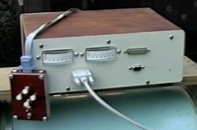
I'm an electrical engineer, who writes software for a living, so the computer and electronic parts of this project weren't too scary. Making the PC board was made easier, though by using the fine board artwork that Berthold Hamburger made available on his website. A new board, with optoisolation and field derotation, is now available from Mel's website at: http://zebu.uoregon.edu/~mbartels/altaz/pcb.html
I built Mel's drive without much of a machine shop. I have a drill press and a good dial caliper, but no lathe or mill. Most of the metalwork was done with hacksaw and file. The difficult machining was contracted to a master machinist, Andy Saulietis, who made the drive rollers, the HDPE worm gears and hubs, and some other parts. Andy's telescope machining business can be contacted by email at iss@pvtnetworks.net (highly recommended)
Bill Prewitt, 13 June, 2000